Virtual Vents: The Changing Face of Hydrothermalism Revealed

3D Seafloor Mapping with Structured Light

SOI/Alexander Duda
Mar. 26 2016


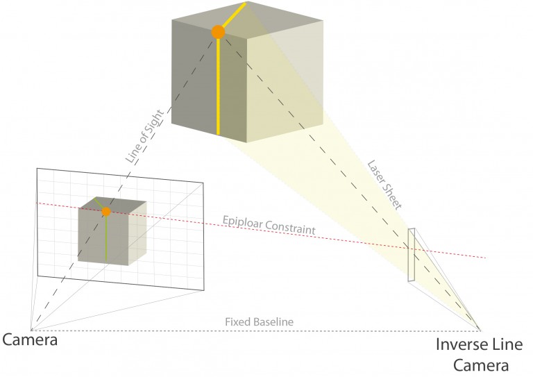
One of the primary goals of this research cruise is to create high resolution 3D maps of vent groups found in Tongan waters. For this purpose, the remotely operated underwater vehicle ROPOS has been equipped with additional sensors during the transit to the Niua Volcanic Complex – these sensors will allow us to map 3D underwater environments with millimeter resolution. The tools include a structured light system that uses a camera and a laser line projector to estimate 3D scene depth via triangulation. This system is my responsibility. 

ROV ROPOS has been equipped with additional sensors during the transit to the Niua Volcanic Complex allowing to map 3D underwater environments with millimeter resolution. This includes a structured light system using a camera and a laser line projector to estimate 3D scene depth via triangulation.
ROV ROPOS has been equipped with additional sensors during the transit to the Niua Volcanic Complex allowing to map 3D underwater environments with millimeter resolution. This includes a structured light system using a camera and a laser line projector to estimate 3D scene depth via triangulation.SOI/Alexander Duda
One of the thousands recorded raw images of the Niua Volcanic Complex from the Virtual Vents Research cruise. Here, a blue line near the bottom indicates that the seabed is very close to the camera and a blue line near to the top of the image means that the seabed is far away.
One of the thousands recorded raw images of the Niua Volcanic Complex from the Virtual Vents Research cruise. Here, a blue line near the bottom indicates that the seabed is very close to the camera and a blue line near to the top of the image means that the seabed is far away.SOI/Alexander Duda

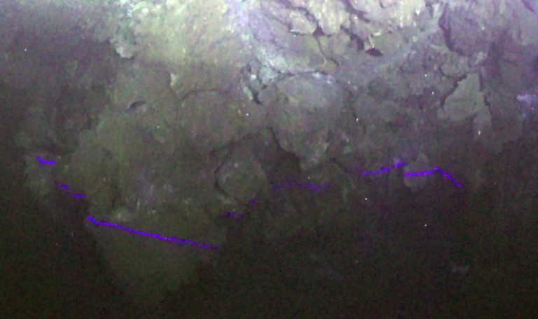
During the first days at sea, the structured light system was calibrated and several regions were mapped from an altitude of about 5 meters to the seafloor. One of the thousands of recorded raw images is shown at right. Here, a blue line near the bottom indicates that the seabed is very close to the camera and a blue line near to the top of the image means that the seabed is far away.

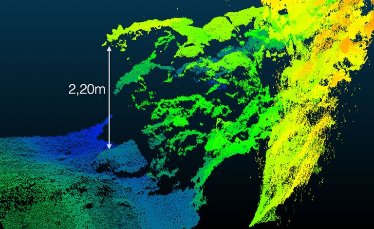
By automatically extracting this information from every recorded image, the seabed can be represented as a georeferenced 3D pointcloud, which allows us to directly size all mapped objects. In case of the pointcloud shown below, a false color representation was chosen to visualize different seafloor heights (blue = low, yellow = high).

By extracting information about distance from every recorded image, the seabed can be represented as a geo-referenced 3D pointcloud, allowing to directly size all mapped objects. In the pointcloud shown, here a false color representation was chosen to visualize different seafloor heights (blue = low, yellow =high).
By extracting information about distance from every recorded image, the seabed can be represented as a geo-referenced 3D pointcloud, allowing to directly size all mapped objects. In the pointcloud shown, here a false color representation was chosen to visualize different seafloor heights (blue = low, yellow =high).SOI/Alexander Duda

In the next days, we have to process the recorded data from all our systems (already reaching several Terabytes). We will then decide which areas have to be revisited to get almost 100% coverage of the mapping area.


Share This